Introduction
This document provides instructions for creating Airship manifests for new sites.
Process
The process of creating manifests that would be used for deployment involves the following steps:
- Preparation - Cataloging the hardware, network topology, public keys, and so on.
- Authoring - Customizing the templates using the information collected in the Preparation phase.
- Auto-Generation - Generating certificates.
- Publishing - Publishing to OPNFV-Airship's Repository.
Preparation
The user needs to collect the following information before starting the authoring process.
- IPMI details of the Nodes. For Intel pods, this information is available in the wiki. Example: Intel POD15
- Disk Information. User can boot into any system and run this command: sudo lshw -c disk
- PCI IDs of NICs. User can boot into any system and run this command: sudo lshw -c network businfo
- The topology and underlay networking details. For Intel pods, this information is available in the wiki. Example: Intel POD15
- Public Keys of Users.
- Any custom requirements with regards to software.
Assumptions
- All the hardware are uniform.
- Same number of NICs with the same PCI IDs.
- Same number of disks with the same addresses.
- Everything is named and their names are used for reference. In Airship, the filename is not important, but the name in the 'schema' (found in schema/metadata/name) is important.
Authoring: Customizing the Parameters
Deployment Configuration and Strategy
This section is added mainly for completeness. User may choose to configure these values if required. For example, with a slow internet access site, some timeouts may be modified. Or, If user wants to perform some kind of check between two actions.
| Parameter | Subcategory-1 | Subcategory-2 | Description | Example Value |
|---|---|---|---|---|
| physical_provisioner | ||||
| deployment_strategy | Name of the strategy to use. User can use the one that is defined in airshipit/treasuremap/global/deployment See below. | deployment-strategy | ||
| deploy_interval | The seconds delayed between checks for progress of the step that performs deployment of servers | 30 | ||
| deploy_timeout | The maximum seconds allowed for the step that performs deployment of all servers | 3600 | ||
| destroy_interval | The seconds delayed between checks for progress of destroying hardware nodes | 30 | ||
| destroy_timeout | The maximum seconds allowed for destroying hardware nodes | 900 | ||
| join_wait | The number of seconds allowed for a node to join the Kubernetes cluster | 0 | ||
| prepare_node_interval | The seconds delayed between checks for progress of preparing nodes | 30 | ||
| prepare_node_timeout | The maximum seconds allowed for preparing nodes | 1800 | ||
| prepare_site_interval | The seconds delayed between checks for progress of preparing the site | 10 | ||
| prepare_site_timeout | The maximum seconds allowed for preparing the site | 300 | ||
| verify_interval | The seconds delayed between checks for progress of verification | 10 | ||
| verify_timeout | The maximum seconds allowed for verification | 60 | ||
| kubernetes | ||||
| node_status_interval | ||||
| node_status_timeout | ||||
| kubernetes_provisioner | ||||
| drain_timeout | Maximum seconds allowed for draining a node | 3600 | ||
| drain_grace_period | Seconds provided to Promenade as a grace period for pods to cease | 1800 | ||
| clear_labels_timeout | Maximum seconds provided to Promenade to clear labels on a node | 1800 | ||
| remove_etcd_timeout | Maximum seconds provided to Promenade to allow for removing etcd from a node | 1800 | ||
| etcd_ready_timeout | Maximum seconds allowed for etcd to reach a healthy state after a node is removed | 600 | ||
| armada+ | ||||
| get_releases_timeout | Timeout for retrieving Helm charts releases after deployment | 300 | ||
| get_status_timeout | Timeout for retrieving status | 300 | ||
| manifest+ | Name of the manifest document that the workflow will use during site deployment activities | 'full-site' | ||
| post_apply_timeout | 7200 | |||
| validate_design_timeout | Timeout to validate the design | 600 | ||
| Deployment-Strategy | ||||
| groups | Named sets of nodes that will be deployed together | |||
| name | Name of the group | masters | ||
| critical | If this group is required to continue to additional phases of deployment | true | ||
| depends_on | Group names that must be successful before this group can be processed | [] | ||
| selectors | A list of identifying information to indicate the nodes that are members of this group. Each selector has following 4 filter values | |||
| node_names | Name of the node | node01 | ||
| node_labels | Label of the node | ucp_control_plane: enabled | ||
| node_tags | Tags in Node | control | ||
| rack_names | Name of the rack | rack01 | ||
| success_criteria | A list of identifying information to indicate the nodes that are members of this group. When no criteria are specified, it means that no checks are done. Processing continues as if nothing is wrong | |||
| percent_successful_nodes | The calculated success rate of nodes completing the deployment phase. | 75 would mean that 3 of 4 nodes must complete the phase successfully | ||
| minimum_successful_nodes | An integer indicating how many nodes must complete the phase to be considered successful | 3 | ||
| maximum_failed_nodes | An integer indicating a number of nodes that are allowed to have failed the deployment phase and still consider that group successful. | 0 | ||
Typical Ordering of groups is shown below.
 __________     __________________
| ntp-node |   | monitoring-nodes |
 ----------     ------------------
     |
 ____V__________
| control-nodes |
 ---------------
     |_________________________
         |                     |
   ______V__________     ______V__________
  | compute-nodes-1 |   | compute-nodes-2 |
   -----------------     -----------------
Profiles
There are two important categories of profiles that the user should create to match their environment:
- Hardware (site/<site_name>/profiles/hardware/<profile_name>.yaml)
- Host site/<site_name>/profiles/host/<profile_name(s)>.yaml
Hardware Profile
Under the hardware profile, user can provide details about the server, and a few device (network and disk) aliases. User can contact the administrator to obtain this information. Otherwise, one has to obtain this information from the 'lshw' command. For example, to know the NIC names and PCI IDs: sudo lshw -c network -businfo
Once the user has the hardware information, it is used to configure the following parameters:
Server
| Parameter | Description | Example Value |
|---|---|---|
| vendor | Vendor of the server chassis | Intel |
| generation | Generation of the chassis model | '4' |
| hw_version | Version of the chassis model within its generation | '3' |
| bios_version | The certified version of the chassis BIOS | 'SE5C .... |
| boot_mode | Mode of the default boot of hardware - bios, uefi | bios |
| bootstrap_protocol | Protocol of boot of the hardware - pxe, usb, hdd | 'pxe |
| pxe_interface | Which interface to use for network booting within the OOB manager, not OS device | 0 |
Device-Aliases
NICs
User can categorize the NICs in the hardware as either control-plane NICs or dataplane NICs. There can be one or more NICs in each category. For example, the following could be defined: ctrl_nic1, ctrl_nic2, ctrl_nic3, and data_nic1, data_nic2, data_nic3, and so on. It is better to use names that are self-explanatory. For example, if you have a separate NIC for PXE, name it as pxe_nic. This categorization will be referred in the host-profiles. For every NIC defined, the below information can be configured.
| Parameter | Description | Example Value |
|---|---|---|
| address | The PCI address of the NIC | 0000:04:00.0 |
| dev_type | Description of the NIC | 'I350 Gigabit Network Connection' |
| bus_type | The bus supported | 'pci' |
Disks
The disks can be either bootdisk or datadisk(s). Similar to NICs, self-explanatory names should be chosen. For example, cephjournal1 can be the name for one of the disks use as one the Ceph journals.
For every disk defined, the below information can be configured:
| Parameter | Description | Example Value |
|---|---|---|
| address | The bus address of the disk | 0:2.0.0 |
| dev_type | Description of the disk. | 'INTEL SSDSC2BB48' |
| bus_type | The bus supported | 'scsi' |
Others
| Parameter | Subcategory-1 | Subcategory-2 | Description | Example Value |
|---|---|---|---|---|
| cpu_set | ||||
| kvm | '4-43,48-87' | |||
| huge_pages | ||||
| dpdk | ||||
| size | '1G' | |||
| count | 32 |
Host Profiles
The following items are covered:
- Mapping NICs of the host to the networks it would belong to. NOTE: For definition of network, please refer to Networks section below.
- How the Bootdisk is partitioned.
- Which software components are enabled on a particular host.
- What hardware profile that host is using.
- Platform-specific configuration for the host.
For the majority of the cases, you only need two host profiles - Dataplane and Control Plane. Of course, the user can create more than 2 and use them accordingly. The below table summarizes the configurable parameters for the host profiles.
Note: One host profile can adopt values from other host profile.
| Parameter Category | Subcategory-1 | Subcategory-2 | Subcategory-3 | Subcategory-4 | Description | Example Value |
|---|---|---|---|---|---|---|
| hardware_profile | NA | NA | The hardware profile used by the host | intel_2600.yaml | ||
| primary_network | NA | NA | The main network used for administration | dmz | ||
| Interfaces | NA | NA | Define each interface of the host in detail. | |||
| Name | NA | Name of the Interface | dmz, data1 | |||
| device_link | The name of the networkLink that will be attached to this interface. NetworkLink definition includes part of the interface configuration such as bonding (see below) | dmz, data1 | ||||
| slaves | NIC Aliases. The list of hardware interfaces used for creating this interface. This value can be a device alias defined in the HardwareProfile or the kernel name of the hardware interface. For bonded interfaces, this would list all the slaves. For non-bonded interfaces, this should list the single hardware interface used | ctrl_nic1, data_nic1 | ||||
| networks | This is the list of networks to enable on this interface. If multiple networks are listed, the NetworkLink attached to this interface must have trunking enabled or the design validation will fail. | dmz, private, management | ||||
| storage | Either in a HostProfile or BaremetalNode document. The storage configuration can describe the creation of partitions on physical disks, the assignment of physical disks and/or partitions to volume groups, and the creation of logical volumes. | |||||
physical_devices* | A physical device can either be carved up in partitions (including a single partition consuming the entire device) or added to a volume group as a physical volume. Each key in the physical_devices mapping represents a device on a node. The key should either be a device alias defined in the HardwareProfile or the name of the device published by the OS. The value of each key must be a mapping with the following keys | |||||
| labels | A mapping of key/value strings providing generic labels for the device | bootdrive: true | ||||
| volume_group | A volume group name to add the device to as a physical volume. Incompatible with the partitions specification | |||||
| partitions* | A sequence of mappings listing the partitions to be created on the device. Incompatible with volume_group specification | |||||
| name | Metadata describing the partition in the topology | 'root | ||||
| size | The size of the partition. | '30g' | ||||
| part_uuid | A UUID4 formatted UUID to assign to the partition. If not specified, one will be generated | |||||
| volume_group | name assigned to a volume group | |||||
| labels | ||||||
| bootable | Boolean whether this partition should be the bootable device | true | ||||
| filesystem | An optional mapping describing how the partition should be formatted and mounted | |||||
| mountpoint | Where the filesystem should be mounted. If not specified the partition will be left as a raw device | '/' | ||||
| fstype | The format of the filesystem. Defaults to ext4 | 'ext4' | ||||
| mount_options | fstab style mount options. Default is ‘defaults’ | 'defaults' | ||||
| fs_uuid | A UUID4 formatted UUID to assign to the filesystem. If not specified, one will be generated | |||||
| fs_label | A filesystem label to assign to the filesystem. Optional. | |||||
| volume_groups | ||||||
| vg_uuid | A UUID4 format uuid applied to the volume group. If not specified, one is generated | |||||
| logical_volumes* | A sequence of mappings listing the logical volumes to be created in the volume | |||||
| name | Used as the logical volume name | |||||
| lv_uuid | A UUID4 format uuid applied to the logical volume: If not specified, one is generated | |||||
| size | The logical volume size | |||||
| filesystem | A mapping specifying how the logical volume should be formatted and mounted | |||||
| mountpoint | Same as above. | |||||
| fstype | ||||||
| mount_options | ||||||
| fs_uuid | ||||||
| fs_label | ||||||
| platform | Define the operating system image and kernel to use as well as customize the kernel configuration | |||||
| image | Image name | 'xenial' | ||||
| kernel | Kernel Version | 'hwe-16.04' | ||||
| kernel_params | A mapping. Each key should either be a string or boolean value. For boolean true values, the key will be added to the kernel parameter list as a flag. For string values, the key:value pair will be added to the kernel parameter list as key=value | kernel_package: 'linux-image-4.15.0-46-generic' | ||||
| oob | The ipmi OOB type requires additional configuration to allow OOB management | |||||
| network | The node network used for OOB access. | oop | ||||
| account | Valid account that can access the BMC via IPMI over LAN | root | ||||
| credential | Valid password for the account that can access the BMC via IPMI over LAN | root | ||||
| spec | host_profile | Name of the HostProfile that this profile adopts and overrides values from. | defaults | |||
| metadata | ||||||
| owner_data | ||||||
| <software-component-name> enabled/disabled | openstack-l3-agent: enabled |
Nodes
This is defined under Baremetal. Node network attachment can be described in a HostProfile or a BaremetalNode document. Node addressing is allowed only in a BaremetalNode document.
Hence, this focuses mostly on addressing. Nodes adopt all values from the profile that it is mapped to and can then again override or append any configuration that is specific to that node.
A separate schema, as described by the following table, is created for each node of the deployment.
| Parameter Category | Subcategory-1 | Subcategory-2 | Subcategory-3 | Subcategory-4 | Description | Example Value |
|---|---|---|---|---|---|---|
| addressing* | Specifies IP address assignments for all the networks. Networks can be omitted from this paramenter, in which case the interface attached to the omitted network is configured as link up with no address | |||||
| address | It defines a static IP address or dhcp for each network. A node should have a configured layer 3 interface on. | 10.10.100.12 or dhcp | ||||
| network | The Network name. | oob, private, mgmt, pxe, etc. | ||||
| host_profile | Which host profile to assign to this node. | cp-intel-pod10 | ||||
| metadata | ||||||
| tags | 'masters' | |||||
| rack | pod10-rack |
*: Array of Values.
Network Definition
Network
| Parameter | Subcategory | Description | Example Value |
|---|---|---|---|
| cidr | Classless inter-domain routing address for the network | 172.16.3.0/24 | |
| ranges* | Defines a sequence of IP addresses within the defined cidr. Ranges cannot overlap. | ||
| type | The type of address range (static, dhcp, reserved) | static | |
| start | The starting IP of the range, inclusive. | 172.16.3.15 | |
| end | The last IP of the range, inclusive | 172.16.3.200 | |
| dns | Used for specifying the list of DNS servers to use if this network is the primary network for the node. | ||
| domain | A domain that can be used for automated registration of IP addresses assigned from this Network | opnfv.org | |
| servers | A comma-separated list of IP addresses to use for DNS resolution | 8.8.8.8 | |
| dhcp_relay | DHCP relaying is used when a DHCP server is not attached to the same layer 2 broadcast domain as nodes that are being PXE booted. The DHCP requests from the node are consumed by the relay (generally configured on a top-of-rack switch) which then encapsulates the request in layer 3 routing and sends it to an upstream DHCP server. The Network spec supports a dhcp_relay key for Networks that should relay DHCP requests. | ||
| self_ip | |||
| upstream_target | IP address must be a host IP address for a MaaS rack controller. The upstream target network must have a defined DHCP address range | ||
| mtu | Maximum transmission unit for this Network. Must be equal or less than the mtu defined for the hosting NetworkLink. | 1500 | |
| vlan | If a Network is accessible over a NetworkLink using 802.1q VLAN tagging, the vlan attribute specified the VLAN tag for this Network. It should be omitted for non-tagged Networks | '102' | |
| routedomain | Logical grouping of L3 networks such that a network that describes a static route for accessing the route domain will yield a list of static routes for all the networks in the routedomain. See the description of routes below for more information | storage | |
| routes* | Defines a list of static routes to be configured on nodes attached to this network. The routes can be defined in one of two ways: an explicit destination subnet where the route will be configured exactly as described or a destination routedomain where Installer will calculate all the destination L3 subnets for the routedomain and add routes for each of them using the gateway and metric defined. | ||
| subnet | Destination CIDR for the route | 0.0.0.0/0 | |
| gateway | The gateway IP on this Network to use for accessing the destination | 172.16.3.1 | |
| metric | The metric or weight for this route | 10 | |
| routedomain | Use this route’s gateway and metric for accessing networks in the defined routedomain. | storage |
Network Link
The NetworkLink defines layer 1 and layer 2 attributes that should be in-sync between the node and the switch. Each link can support a single untagged VLAN and 0 or more tagged VLANs
| Parameter | Subcategory | Description | Example Value |
|---|---|---|---|
| bonding | Describes combining multiple physical links into a single logical link | ||
| mode | What bonding mode to configure
| 802.3ad | |
| hash | The link selection hash. Supported values are layer3+4, layer2+3, layer2. | layer3+4 | |
| peer_rate | How frequently to send LACP control frames. Supported values are fast and slow. | fast | |
| mon_rate | Interval between checking link state in milliseconds. | 100 | |
| up_delay | Delay in milliseconds between a link coming up and being marked up in the bond. > mon_rate | 200 | |
| down_delay | Delay in milliseconds between a link going down and being marked down in the bond. > mon_rate | 200 | |
| mtu | Maximum transmission unit for the link. It must be equal to or greater than the MTU of any VLAN interfaces using the link. | 9000 | |
| linkspeed | Physical layer speed and duplex. | auto | |
| trunking | How multiple layer 2 networks will be multiplexed on the link | ||
| mode | Can be disabled for no trunking or 802.1q for standard VLAN tagging | 802.1q | |
| default_network | For mode: disabled, this is the single network on the link. For mode: 802.1q this is optionally the network accessed by untagged frames. | ||
| allowed_networks* | A sequence of network names listing all networks allowed on this link. Each Network can be listed on one and only one NetworkLink |
Software
OpenStack services are deployed as containers. To manage these containers, various container management platforms such as Kubernetes are used.
Airship uses OpenStack on Kubernetes (OOK). For deployment/configuration of services/applications/pods (in this case OpenStack, monitoring, and so on) on Kubernetes, users have two options: (a) Kolla-Kubernetes or (b) OpenStack Helm. Both options use Helm for packaging the Kubernetes definitions for each service. However, OpenStack Helm uses Helm charts, whereas Kolla-Kubernetes uses Ansible for deployment/orchestration. Airship uses Helm charts. Accordingly, under software, user configurations fall under two important categories: Charts and Configurations.
Charts
Kubernetes
For a Kubernetes system (Namespace: kube-system), user just has to do some substitutions for the control nodes. In this definition, a list of control plane nodes (genesis node and master node list) is created. Calico etcd runs on these nodes, and certs are be required. It is assumed that Airship sites will have 3 control plane nodes, so this should not need to change for a new site. User only has to perform some substitutions.
First he has to create a mapping. The mapping would be:
Source (as mentioned in commonaddress.yaml) | Destination |
|---|---|
| .genesis.hostname | .values.nodes[0].name |
| .masters[0].hostname | .values.nodes[1].name |
| .masters[1].hostname | .values.nodes[2].name |
Source | Destination |
|---|---|
| certificate of calico-etcd-<podname>-node1 | .values.nodes[0].tls.client.cert |
| certificate-key calico-etcd-<podname>-node1 | .values.nodes[0].tls.client.key |
| certificate of calico-etcd-<podname>-node1-peer | .values.nodes[0].tls.peer.cert |
| certificate-key of calico-etcd-<podname>-node1-peer | .values.nodes[0].tls.peer.key |
| certificate of calico-etcd-<podname>-node2 | .values.nodes[1].tls.client.cert |
| certificate-key calico-etcd-<podname>-node2 | .values.nodes[1].tls.client.key |
| certificate of calico-etcd-<podname>-node2-peer | .values.nodes[1].tls.peer.cert |
| certificate-key of calico-etcd-<podname>-node2-peer | .values.nodes[1].tls.peer.key |
| certificate of calico-etcd-<podname>-node3 | .values.nodes[2].tls.client.cert |
| certificate-key calico-etcd-<podname>-node3 | .values.nodes[2].tls.client.key |
| certificate of calico-etcd-<podname>-node3-peer | .values.nodes[2].tls.peer.cert |
| certificate-key of calico-etcd-<podname>-node3-peer | .values.nodes[2].tls.peer.key |
Undercloud Platform
TBA
Ceph
TBA
OpenStack Helm Infra
This includes configuring parameters of various infrastructure components, such as Elasticsearch, Fluentbit, Fluentd, Grafana, Ingress, Mariadb, and Prometheus.
User can leave all the values as is.
OpenStack Helm - Compute Kit
Under this, there are three important configurations -
- Libvirt:
- Network Backend: Open vSwitch or SR-IOV.
- Neutron
- Nova
Tenant-Ceph
Config
Under this configuration, user can only set the region name for OpenStack Helm.
| Parameter | Subcategory | Description | Example Value |
|---|---|---|---|
| osh | |||
| region_name | The region name to use. Typically Site name is provided. | intel-pod10 |
PKI-Catalog
| Parameter | Subcategory-1 | Subcategory-2 | Description | Example Value |
|---|---|---|---|---|
| certificate_authorities | ||||
| description | ||||
| certificates | ||||
| document_name | ||||
| description | ||||
| common_name | ||||
| hosts | ||||
| groups | ||||
| keypairs | ||||
| name | ||||
| description |
Secrets
Publickeys of the Users.
Path: site/<site_name>/secrets/publickey/<username>_ssh_public_key.yaml
The public key of the user is added as 'data'.
Passphrases of the users
Path: site/<site_name>/secrets/publickey/<username>_crypt_password.yaml
Put a passphrase for the user as 'data'.
Boot Actions
Boot actions can be more accurately described as post-deployment file placement. This file placement can be leveraged to install actions for servers to take after the permanent OS is installed and the server is rebooted. Including custom or vendor scripts and a SystemD service to run the scripts on first boot or on all boots allows almost any action to be configured.
| Parameter | Subcategory-1 | Subcategory-2 | Description | Example Value |
|---|---|---|---|---|
| signaling | Whether to expect a signal at the completion of this boot action. If set to true for a boot action that does not send a signal, it will extend the deployment step and consider the boot action failed. | true | ||
| assets | A list of data assets. | |||
| items | ||||
| path | If type is unit, it is a SystemD unit, such as a service, that will be saved to path and enabled via systemctl enable [filename] | |||
| location | (see data) | |||
| type | boot action framework supports assets of several types - 'unit','file', 'pkg_list' . pkg_list is a list of packages | 'file' | ||
| data | The asset contents can be sourced from either the in-document data field of the asset mapping or dynamically generated by requesting them from a URL provided in location. | |||
| location_pipeline | The boot action framework supports pipelines to allow for some dynamic rendering. There are separate pipelines for the location field to build the URL that referenced assets should be sourced from and the data field (or the data sourced from resolving the location field). | template | ||
| data_pipeline | The For 'template' - Treat the data element as a Jinja2 template and apply a node context to it. The defined context available to the template is below. | base64_encode', 'template', 'base64_decode', 'utf8_encode','utf8_decode' | ||
| permissions | If type is file, it is saved to the filesystem at path and set with permissions. | |||
| node_filter | Filter for selecting to which nodes this boot action will apply. If no node filter is included, all nodes will receive the boot action. Otherwise, it is only the nodes that match the logic of the filter set. | |||
| filter_set_type | Either intersection|union | union | ||
| filter_set items | ||||
| filter_type | Same as filter_set_type. | |||
| node_names | Names of the node. | |||
| node_tags | Node tags | |||
| node_labels | Node labels. | |||
| rack_names | Rack Names | |||
| rack_labels | Rack Labels |
Rack
| Parameter | Subcategory | Description | Example Value |
|---|---|---|---|
| tor_switches | For one or more switches, define the following. | ||
| mgmt_ip | IP address of the management port | 1.1.1.1 | |
| sdn_api_uri | The URI for SDN based configuration | https://polo.opnfv.org/switchmgmt?switch=switch01name | |
| location | |||
| clli | Common Language Location Identifier Code - used within the North American telecommunications industry to specify the location and function of telecommunications equipment. | HSTNTXMOCG0 | |
| grid | The grid code. | EG12 | |
| local_networks* | Networks wholly contained to this rack. Nodes in a rack can only connect to local_networks of that rack | pxe_network1 |
Region
| Parameter | Subcategory | Description | Example Value |
|---|---|---|---|
| tag_definitions* | |||
| tag | |||
| definition_type | lshw_xpath | ||
| definition | |||
| authorized_keys* | |||
| repositories | List of SSH keys which MaaS will register for the built-in "ubuntu" account during the PXE process. This list is populated by substitution, so the same SSH keys do not need to be repeated in multiple manifests. | ||
| remove_unlisted | Whether to remove the unlisted packages | true | |
| repo_type+ | |||
| url+ | |||
| distributions | |||
| subrepos | |||
| components | |||
| gpgkey | |||
| arches+ | |||
| options |
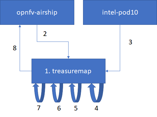
Generating Certificates
Generating certificates involves the following steps:
- 1. Get airship treasuremap to the jumpserver. git clone https://github.com/airshipit/treasuremap.git
- 2. Copy type/cntt folder from opnfv-airship repo to cloned airship treasuremap repo under type
- 3. mv site defn. For pod10 to treasuremap
- 4. sudo tools/airship pegleg site -r /target collect intel-pod10 -s intel-pod10_collected
- 5. mkdir intel-pod10_certs
- 6. sudo tools/airship promenade generate-certs -o /target/intel-pod10_certs /target/intel-pod10_collected/*.yaml
- 7. cp intel-pod10_certs/*.yaml site/intel-pod10/secrets/certificates/
- 8. mv site/intel-pod10 ../airship/site/
Publishing
TBA